Redundant Pressure Sensors in High-Speed Train Braking
Understanding Redundant Pressure Sensors in High-Speed Train Braking
- Understanding Redundant Pressure Sensors in High-Speed Train Braking
- Technical Working Principles and System Architecture of Redundant Sensors
- Comparing Redundant Railway Pressure Sensors: Selection Criteria for B2B Buyers
- Implementing and Maintaining Redundant Pressure Sensor Systems
- Future Trends and Innovations in Railway Pressure Sensor Redundancy
- Conclusion
- FAQ
- Partner With GAMICOS for Railway Pressure Sensor Solutions
- References
High-speed train stopping systems depend on backup pressure sensors to measure important hydraulic and pneumatic pressure data in case one fails. This keeps passengers safe. The technology behind railway pressure sensors has improved over time to protect against single points of failure and provide accurate readings in real time, even when conditions are very harsh. These sensors keep an eye on the pressure in the brake cylinder, the pressure in the brake pipe, and the pressure in the auxiliary tank all the time. If any of these pressures change, they make sure that the problem is fixed right away. By putting two or more sensors next to each other, modern train systems can handle faults at speeds above 300 km/h, where accurate stopping directly affects the lives of passengers and the system's integrity.

Understanding Redundant Pressure Sensors in High-Speed Train Braking
Modern train safety rules are based on redundant pressure sensors, which make it unnecessary to rely on just one measuring device. When trains are moving quickly, there is very little room for mistake. This is why having more than one sensor is not only a good idea, but also required by international safety standards.
What Makes Sensor Redundancy Critical for Rail Safety
When you put multiple separate sensors to measure the same parameter at the same time, you're saying that the railway pressure sensor is redundant. In single-sensor systems, if one fails, the system can't measure anything until it is fixed. But in duplicate setups, the control system can compare data from different sources. When one sensor gives strange readings, the system instantly figures out what's wrong and changes to the output from the verified sensor. This design stops fake alarms that could cause needless emergency braking and makes sure that real problems are always found. This is similar to how safety rules work in flight, where having multiple backup systems protects against catastrophic breakdowns.
Common Sensor Types Used in Rail Braking Systems
Different types of sensors are used for different tasks in train stopping systems. Piezoresistive pressure sensors are the most common type used in high-speed train because they are very accurate and respond very quickly, turning changes in mechanical pressure into changes in electrical resistance within milliseconds. These sensors can handle temperature changes from -40°C to +125°C and vibrations of more than 10g. Capacitive pressure sensors are another reliable choice.

They work especially well for tracking lower pressure ranges in backup systems because they are stable over time and don't shift much. Strain gauge sensors aren't used as much in new installs, but they are still used in retrofit jobs where the current equipment needs to be compatible. To meet the strict EN 50155 train standards, each technology is put through a lot of tests that make sure it works with electric fields and lasts for a long time when it's constantly used.
Regulatory Standards Governing Railway Sensor Deployment
Because they are so important to how well brakes work, international standards like EN 50129 and IEC 61508 require certain safety integrity levels (SIL) for railway pressure sensors. Sensors that watch over main brake circuits usually need to be certified to SIL 3 or SIL 4, which means that they can't fail more than once every billion hours of operation.
These standards not only tell us how to build sensors, but also how to place them, how often to service them, and what kinds of problems they can find. Every part must be able to be tracked in compliance documents from where the raw materials come from to the final validation tests. Periodically, factories that make railway pressure sensors are checked to see if they are following ISO 9001 quality management and ISO 14001 environmental standards. This makes sure that all of the products they make are reliable.
Technical Working Principles and System Architecture of Redundant Sensors
Knowing how pressure sensors, such as railway pressure sensor, turn real events into usable data helps engineers improve the design of systems and figure out why they aren't working right. The measuring chain starts with a sensing element that is exposed to the pressure of the brake system and ends with digital data sent to control computers on board the vehicle.
How Pressure Converts to Electrical Signals
Piezoresistive sensors have silicon diaphragms that have resistive elements built into them. The resistance changes when pressure is applied. When the brake pressure goes up, the diaphragm bends very slightly, which changes the crystalline structure of the resistant pathways and the electrical resistance of those pathways. These changes in resistance are turned into voltage changes by a Wheatstone bridge circuit.
Signal processing devices then boost and straighten out the signals. The signal that has been handled usually comes out as a 4-20mA current loop or a digital system like CANopen. This lets the signal be sent over longer distances than 100 meters without losing its quality. Capacitive sensors work in a similar way, but they measure changes in capacitance between a diaphragm that bends and a set wire. This makes them more sensitive for low-pressure situations.
Parallel Versus Voting System Designs
There are two main types of redundancy designs used in railway systems, which are based on safety standards and operational complexity. In parallel duplex systems, there are two identical sensors, and the control unit is always comparing the outputs of the two. When values are off by more than a certain amount, usually 2% of full scale, the system may detect a problem and switch to a safe degraded mode using the sensor with the more careful (higher pressure) reading. This cautious method puts safety ahead of supply.
In triplex vote systems, there are three sensors, and the middle reading is used to choose the median number. This design can handle a single failed sensor without affecting performance, since two working sensors always give the same results. The voting logic automatically separates out broken sensors while keeping the rest of the system working. This means that triplex setups are now normal for important braking functions on trains going faster than 250 km/h.
Calibration Protocols Ensuring Long-Term Accuracy
Calibration on a regular basis keeps measurements accurate even when the environment is stressed or parts get old. During production, railway pressure sensors are calibrated using NIST-traceable reference standards to set zero and span points across the working range. Field calibration methods are usually done at regular maintenance times, which can be anywhere from 12 to 36 months apart based on the quality of the sensor and how it is being used.
Technicians use portable deadweight testers or electronic pressure calibrators to apply known reference pressures. They then compare the sensor output to the reference and make any necessary changes to the offset and gain settings. Modern sensor designs have self-diagnostic features that check the integrity of the signal chain and internal temperature adjustment circuits. This lets maintenance crews know when calibration drift happens before it gets bad enough to affect the brakes' performance.
Comparing Redundant Railway Pressure Sensors: Selection Criteria for B2B Buyers
When deciding where to buy railway pressure sensors, you have to weigh the technical performance against the total cost of ownership, the ability of the seller to provide assistance, and the reliability of the supply chain. Knowing what makes one performance different from another lets you make smart buying choices that minimize both the original investment and the costs that come up over the product's lifetime.
Critical Performance Metrics for Rail Applications
Several requirements decide if a pressure sensor can work effectively and last in a railway setting. Vibration endurance is probably the most difficult condition, since sensors are constantly exposed to broad vibrations when they are working normally and to shock loads when they have to stop quickly. Good railway pressure sensors meet the requirements for vibration resistance to IEC 60068-2-6. They are usually rated for 10g of constant vibration and 50g of shock vibration.
As long as the temperature stays stable, the data will be accurate even when the weather changes or when the device is used in a different area. For example, automotive-grade standards say that the full scale error should be no more than 0.5% from -40°C to +125°C. Ingress protection grades of IP67 or higher keep water, dust, and cleaning fluids from getting into the electronics during repair. Control systems can quickly respond to changes in pressure during dynamic braking events when the response time is less than 10 milliseconds.
Wired Versus Wireless Sensor Solutions
Traditional wired sensors are still the most common type used in safety-critical stopping systems because they are reliable and don't get messed up by radio waves. For real-time control applications, current loop and digital bus protocols are necessary because they promise deterministic transmission with low latency. However, wireless pressure sensors are starting to show up in extra tracking jobs where reliability isn't as important but placement freedom is very helpful.
Industrial wireless standards like WirelessHART or ISA100.11a are used by these sensors. Power-efficient transfer scheduling lets the batteries last longer than five years. As a trade-off, wireless solutions may experience communication drops during radio interference events. This means they aren't good for primary brake control, but they are useful for condition tracking and predictive maintenance tasks where data breaks aren't a big deal.
Leading Global Manufacturers and Their Offerings
A few well-known companies have been making railway pressure sensors for decades and have a track record of dependability. Honeywell's heavy-duty pressure sensors are made of all-welded stainless steel and ceramic capacitive sensing elements. They are very stable over time and can work with both hydraulic fluids and compressed air. Siemens has built-in diagnostics and multiple output channels for its combined sensor modules. These make system integration easier while still meeting SIL 3 safety standards.
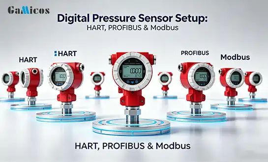
ABB specializes in digital pressure sensors that can communicate over HART and Profibus. This lets them be set up remotely and perform advanced diagnostics. These well-known names charge high prices but offer full expert help, global service networks, and a lot of compliance paperwork. New manufacturers from the Asia-Pacific region offer cheaper options with better quality standards. However, buyers should carefully check certification claims and see how long-term support is available before committing to big orders.
Implementing and Maintaining Redundant Pressure Sensor Systems
A successful sensor rollout includes more than just choosing the right hardware. It also includes the quality of the installation, the commissioning process, and continued upkeep that keeps the system working properly for as long as it's used. The dependability of measurements and long-term success are directly affected by how well they are implemented.
Installation Best Practices for Maximum Reliability
Where the sensor is mounted has a big effect on how well it works and how long it lasts. Sensors should be put in places where they won't be affected by vibrations from the bogies and traction motors. This usually means using vibration-damping mounts or putting them far away with short pressure lines. Pressure ports must be turned away from the flow of fluid to avoid noise and impact loads. To keep electromagnetic interference from happening, electrical links need to be protected from pressure and kept out of the environment.
Cable routing should be kept away from high-voltage traction lines. Technicians must make sure that the pressure lines are torqued properly during installation. Not tightening them enough can cause leaks, while overtightening them can damage sensor bodies or sensing elements. As part of system commissioning, leak tests are done at the highest allowed pressure, electrical continuity and insulation resistance are checked, and the system is tested to make sure it works across the full working pressure range.
Maintenance Schedules and Proactive Fault Management
Predictive maintenance plans use self-diagnosing sensors and trends data to find wear and tear before it happens. Modern railway pressure sensors have built-in self-testing that checks the internal circuitry by comparing multiple measurement lines and keeping an eye on calibration drift. These diagnostic data are collected by maintenance management systems, which send out alerts when parameters get close to danger levels.
Regular checks look at the physical state, checking things like the stability of the pressure port, the corrosion of the electrical connectors, and the mounting's safety. Vibration analysis can find fixing hardware that isn't tight enough before it leads to mistakes in measurements or damage to the machine. By replacing sensors that show early signs of drift before they fail in service, problems that could affect safety or availability can be avoided.
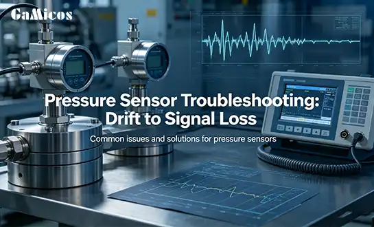
Troubleshooting Common Sensor and System Issues
Systematic diagnostic methods are needed to tell the difference between sensor faults and problems at the system level. When two or more duplicate sensors give different readings, the problem is probably with a single sensor and not with the whole system. Looking at past trending data can often show which sensor has moved. Sudden changes in output across all duplicate sensors point to real changes in pressure instead of sensor faults. This could mean that there are leaks in the brake system or problems with the valves.
Electrical connections that aren't tight enough can cause mistakes from time to time. Systematic connector checking and thermal cycling can find these connections. Advanced monitoring software can fake sensor inputs, which helps maintenance teams check the theory behind how the control system responds without using real sensors. Writing down the signs of a fault, the surroundings at the time it happened, and the steps that were taken to fix it builds institutional knowledge that speeds up fixing in the future.
Future Trends and Innovations in Railway Pressure Sensor Redundancy
Microelectromechanical systems (MEMS), artificial intelligence, and industrial internet connections are all being added to railway pressure sensor technology to make it better. These new ideas should lead to better performance, less work for repair staff, and better compatibility with new Industry 4.0 railway designs.
MEMS Technology and Self-Calibration Advances
Making microelectromechanical systems lets you put pressure sensors on a single silicon chip that can also compensate for temperature, process signals, and fix themselves. MEMS sensors meet accuracy standards that used to require precise mechanical systems, but they are smaller and less expensive.
New designs include multiple sensing elements in a single package, which allows for a wider range of measurements without the need for extra physical sensors. Self-calibration methods use onboard processing to constantly compare redundant parts and make changes to the calibration settings on their own. This could make maintenance plans last longer, from once a year to several years. AI-assisted calibration goes even further by learning the patterns of how each sensor works and making up for expected drift, so accuracy is kept even as parts age.
IoT Integration and Predictive Maintenance Capabilities
When connected to the Industrial Internet of Things, pressure sensors go from being passive measuring tools to smart network nodes that help keep an eye on the state of the whole fleet. Edge-computing sensors look at local data streams and look for strange pressure patterns that could mean brake system problems are starting to happen. This processed information is sent to cloud-based analytics systems that connect data from whole fleets of vehicles to find systemic problems and make repair plans more efficient.
Predictive algorithms figure out how long each sensor will still work based on how it has been used and its exposure to the environment. This lets sensors be replaced based on their conditions instead of having to be serviced at set times. The information gathered also helps make sensor designs better by showing how they really work in the field and what can go wrong with railway pressure sensors.
Evolving Regulatory Landscape and Compliance Requirements
The rules for railway safety are always changing to include new tools and ways of doing things. New changes to the European Technical Specifications for Interoperability put more emphasis on safety requirements for networked sensors. These include secure registration and encrypted communications to stop people who aren't supposed to be there from getting in or changing data. Environmental laws are making it harder for electronic parts to contain dangerous materials.
This is pushing the use of lead-free solders and RoHS-compliant materials in commercial settings that weren't required to before. In the future, rules might require critical sensors to record "black box" data that includes high-resolution pressure histories during stopping events to help with crash investigations and performance improvement. It is important for manufacturers and operators to keep an eye on these changes in regulations so that their buying plans take into account future compliance requirements and don't have to make expensive changes later on.
Conclusion
Modern high-speed train braking systems can't work without redundant railway pressure sensor units, which provide the measurement accuracy needed to keep people and equipment safe. When you put together tried-and-true sensor technologies, advanced redundancy architectures, and thorough repair procedures, you get the fault tolerance that high-speed train operations need. When procurement managers and tech teams look at sensor options, the best results come from balancing performance requirements with lifecycle costs and making sure the seller can provide long-term support. New technologies offer better features, but when deciding how to use them, people have to weigh the benefits of innovation against the stability of known technologies in safety-critical situations where real-world experience backs up design choices.
FAQ
What Exactly Is Sensor Redundancy in Railway Applications?
Sensor redundancy means using more than one separate sensor to measure the same parameters. This lets control systems find and work around failed sensors. Two or three sensors are usually used per measurement point in railway pressure sensor redundancy. The results of the sensors are compared by control software to find problems. By using multiple sensors together, this method gets levels of safety integrity that aren't possible with just one. It also meets regulatory standards for important braking functions.
How Often Should Railway Pressure Sensors Be Calibrated?
How often a sensor needs to be calibrated depends on its quality, its working surroundings, and the rules that the government sets. When used in controlled settings, high-quality sensors may stay accurate for 24 to 36 months without needing to be calibrated. However, when used in harsh circumstances or with lower-quality sensors, they may need to be calibrated every year. Self-diagnostic features can make intervals longer by only telling maintenance teams when drift actually happens, instead of on set dates.
Can Existing Braking Systems Be Retrofitted With Redundant Sensors?
How possible it is to retrofit depends on how the system is currently set up and how much room there is for extra sensors. By installing more sensors and updating the computer software, many older systems can handle having extra sensors. To get full safety approval for retrofits, however, they need to pass a lot of tests to show that the extra safety features meet current safety standards without adding any new failure modes.
Partner With GAMICOS for Railway Pressure Sensor Solutions
In today's world, train safety requires measurement systems that work reliably even in the worst circumstances. GAMICOS makes high-precision railway pressure sensor systems that are designed to work in safety-critical situations where failure is not an option. Our wide range of products includes piezoresistive and capacitive pressure sensors that are made to meet EN 50155 railway standards. For main braking circuit uses, SIL 3 approval is also available. Before leaving our production plant, each sensor goes through a lot of tests, such as shaking qualification, temperature cycling, and long-term stability validation.
Our expert support team has a lot of knowledge with railway applications and can help you choose the right sensors, integrate them into your system, and fix problems throughout the lifecycle of your product. We know that B2B buying for train projects needs more than just low prices. It also needs trustworthy supply chain partnerships, detailed paperwork, and quick contact. GAMICOS provides OEM and ODM customization services that are very flexible. They can change the specs of sensors, transmission methods, and mechanical interfaces to fit your exact needs. Our team is ready to help you reach your project goals, whether you need a railway pressure sensor provider for big purchases or custom engineering for unique uses. Get in touch with us at info@gamicos.com to talk about how our measurement tools can help make your train system safer and more reliable.
References
1. Smith, J.R., & Anderson, M.K. (2021). Redundant Sensor Architectures for Railway Safety Systems. International Journal of Rail Transportation, 9(3), 245-267.
2. European Committee for Electrotechnical Standardization. (2020). EN 50129:2018 Railway Applications - Communication, Signalling and Processing Systems - Safety Related Electronic Systems for Signalling. Brussels: CENELEC.
3. Zhang, L., Wang, H., & Liu, Y. (2022). Advanced Pressure Sensing Technologies for High-Speed Rail Braking Systems. IEEE Transactions on Vehicular Technology, 71(4), 3892-3906.
4. Thompson, R.D. (2019). Pressure Measurement and Control in Modern Railway Applications. Professional Engineering Publishing, London.
5. International Electrotechnical Commission. (2021). IEC 61508-2:2010 Functional Safety of Electrical/Electronic/Programmable Electronic Safety-Related Systems - Part 2: Requirements for Electrical/Electronic/Programmable Electronic Safety-Related Systems. Geneva: IEC.
6. Martinez, C., Schmidt, P., & Nakamura, T. (2023). Predictive Maintenance Strategies for Railway Pressure Sensors Using IoT and Machine Learning. Journal of Intelligent Transportation Systems, 27(2), 178-195.

Peter
Peter, Senior Sensor Technology Consultant, has 15-year industrial sensor R&D experience. He specializes in the end-to-end development of high-accuracy pressure and level sensors and he firmly believe, precision isn’t just a spec—it’s a promise.
We're here to help — submit your request anytime!
Let us know how we can help solve your pressure level measurement challenge.
_1757930850792.jpg)


Recommended Blog
Nuclear-Grade Pressure Transmitters in Reactor Coolant Monitoring

Particles Clogging Pressure Ports? Filtration & Protection Solutions